Universal Signal Conditioning
Drag Drop Image anywhere on Screen with Left Button - Zoom in or Zoom out with Scroll Wheel
Scroll Zoom - Mouse Scroll Wheel can be roated in either direction to Zoom in or Zoom out, refresh page for normal image.
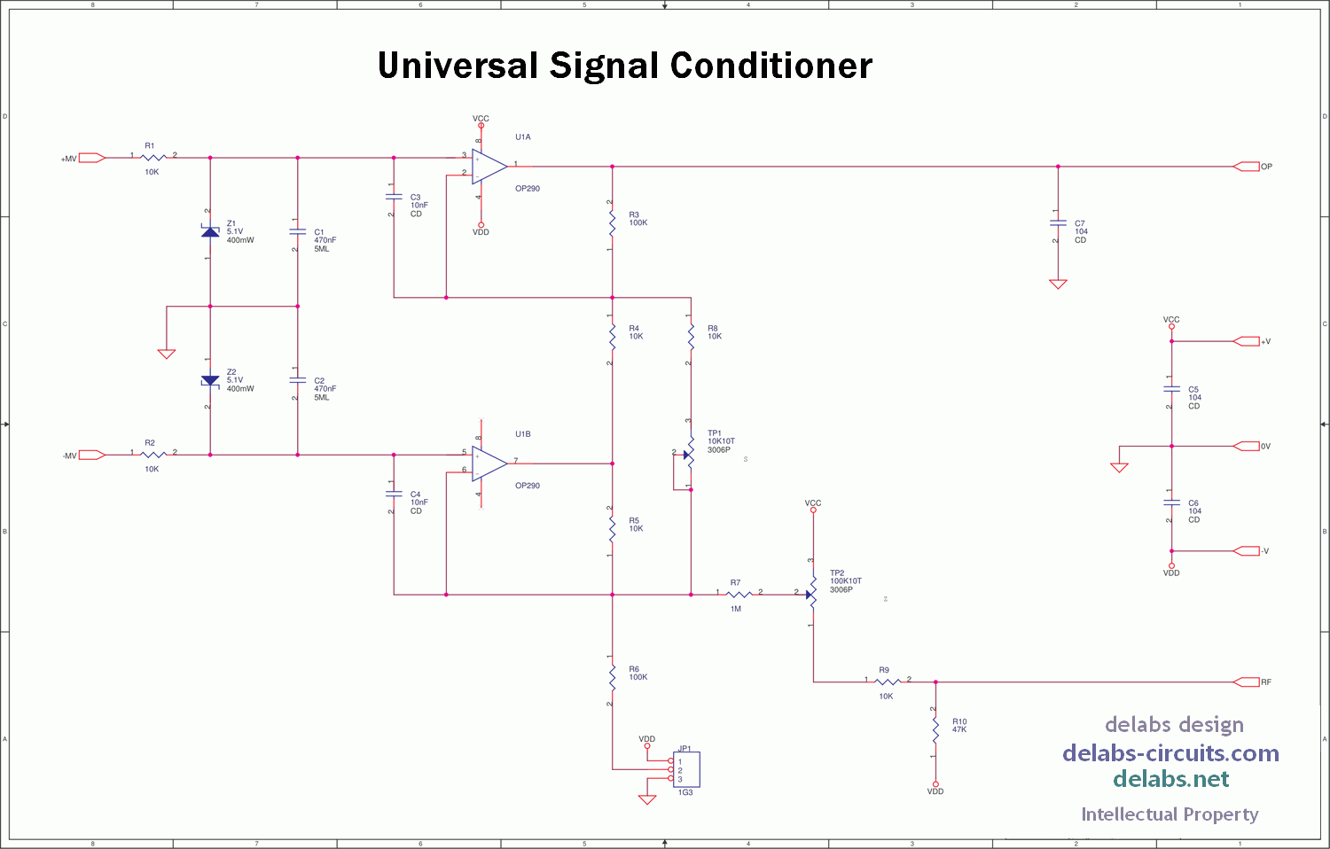
Here is a practical application of the dual differential amp. This circuit is for DC or slow moving DC like Strain Gauge and transducer signals. The RC and Zeners are for protection and clamping. Why and how has been described in other posts here. The high impedance op-amp input cannot face the real world unprotected.
OP07 is always the selection due to the low offset. When the sensor generates data in mV, you cannot afford any error introduced in this front end, right. Here OP290 is used for better performance. This dual opamp is better for building a two wire 4-20mA transmitter. But Op07 is fine for a three wire transmitter which consumes more power.
Observe the Power supply decoupling caps, this is a rule and every chip needs a power cushion. The front end zeners and caps have to be low leakage in many applications, ensure you have such parts or test them.
Opamp Instrumentation Circuits
There are two trimpots, bourns multiturn PCB trimpots. One for Offsett-Null or Zero and other for Span or Gain. You have to tweak them in a alternating sequence as they are interdependent to some extent.
Now your weak transducer with a voice in mV and uV; can meet an A/D “Eye to Eye” and let the whole world know what is the Weight, Temperature, Humidity, Pressure or Moisture Content in the Harsh Real World full of uncertainties..