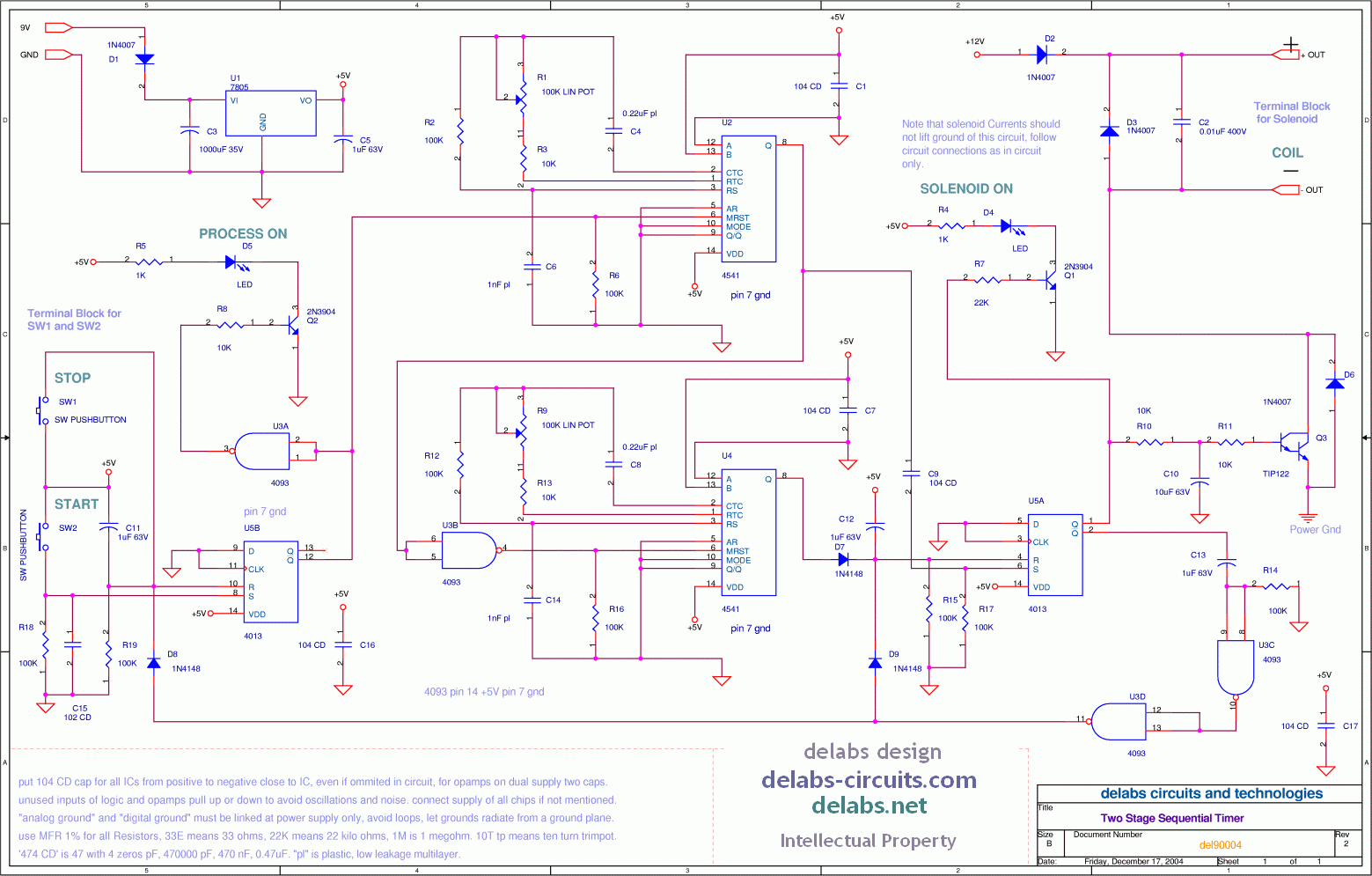
Two Stage Sequential Timer
Drag Drop Image anywhere on Screen with Left Button - Zoom in or Zoom out with Scroll Wheel
Scroll Zoom - Mouse Scroll Wheel can be roated in either direction to Zoom in or Zoom out, refresh page for normal image.
This is an example of a cascaded or sequential timer, here two CD4541 are forming a two stage timer. You can add more in a chain, but better to use a microprocessor or Microcontroller for such a purpose. But make sure EMI-RFI immunity is high for these circuits or wrong resets and sets can make a machine like an Oven or Environment Chamber malfunction and even ruin the job.
See how a Power-On Delay or Off-Delay timer can be built. - Analog Blind Dial On Delay Timer
U5B a flip-flop is used for the control switches Start and Stop to prime or shutdown the sequential cycle. The first timer U2 sets the flip-flop or register U5A after a period T1, this register turns the relay on thru Q3. The second timer U4 which was triggered by the first will reset the U5A after time period T2, U5A then shuts down relay. U5A also then resets entire process thru U3C and U3D
Here is another application need for Timer in my mail archive - Some Cyclic Timer Ideas
In this application two 4541 Timer Chips are Sequentially connected. A Start and Stop User Interface controls the process which is a sequence of Operations. A Solenoid is turned on after a delay and turns off in a second delay.