Synchronized Sample and Hold
Drag Drop Image anywhere on Screen with Left Button - Zoom in or Zoom out with Scroll Wheel
Scroll Zoom - Mouse Scroll Wheel can be roated in either direction to Zoom in or Zoom out, refresh page for normal image.
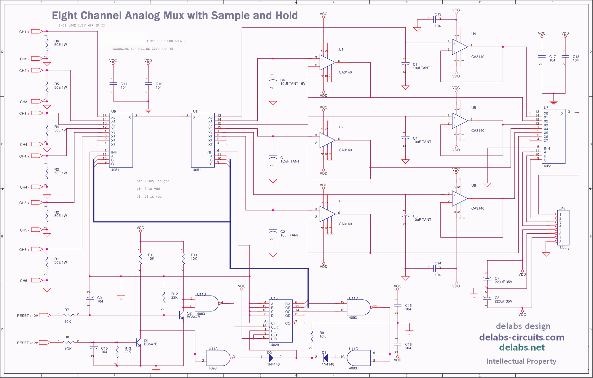
This circuit has two analog mux 4051 operating in synchrony to store an analog value in a low leakage tantalum capacitor. This makes an Analog Memory possible and overall system accuracy of around 2%, which was more than adequate for this process.
The analog value from a temperature transmitter is available for a short duration when it is collected from a rotating system with copper brushes and contacts on the shaft.
The CA3140 with one tera ohm input impedance ensures the accuracy of the analog memory. The scanning by 4029 counter frequently refreshes and updates the analog data.
The 4-20mA signals are converted to voltage by a 50 ohm shunt 1% MFR of 1Watt rating. The clock and reset signals are coming from 12V proximity switches. This is filtered and tamed by a simple transistor circuit. That way the 5V Logic circuit is safe from the 12V external inputs.
Mixed Circuits Analog with Digital
Since both the 4051 operate in tandem the analog value in the tantalum capacitor does not discharge through the 50 ohm shunt current receiver. The CMOS switches offer very high OFF resistance, that makes this circuit workable if properly adapted.