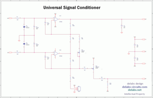
Here is a practical application of the dual differential amp. This circuit is for DC or slow moving DC like Strain Gauge and transducer signals. The RC and Zeners are for protection and clamping. Why and how has been described in other posts here. The high impedance op-amp input cannot face the real world unprotected. OP07 is always the selection due to the low offset. When the sensor generates data in mV, you cannot afford any error introduced in this front end, right.
on: 7/26/2019
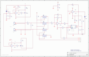
This is the full circuit of a V/F convertor interface for 80C31 SBC. The Mux is configured for selecting between two inputs. It uses analog switch 4066. LF353 along with LM331 form the VCO, you can further study such configuration in the Application Notes of TI/NS.
on: 7/24/2019
This is an example of a cascaded or sequential timer, here two CD4541 are forming a two stage timer. You can add more in a chain, but better to use a microprocessor or Microcontroller for such a purpose. But make sure EMI-RFI immunity is high for these circuits or wrong resets and sets can make a machine like an Oven or Environment Chamber malfunction and even ruin the job.
on: 7/24/2019
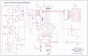
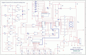
This circuit is built around the chip CD4067, now called 74HC4067, it works like a single pole 16 throw rotary switch that can be controlled digitally. Clamping protection diodes are built in. Use resistors to enable this protection. 16 Analog channels are controlled by a Digital User Interface circuit made of 4093 and 4029. Up/Down and Auto/Man are four Push-buttons. A LED Display to show the Channel Number that is selected.
on: 6/27/2019
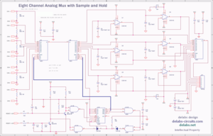
This circuit has two analog mux 4051 operating in synchrony to store an analog value in a low leakage tantalum capacitor. This makes an Analog Memory possible and overall system accuracy of around 2%, which was more than adequate for this process. The analog value from a temperature transmitter is available for a short duration when it is collected from a rotating system with copper brushes and contacts on the shaft.
on: 6/26/2019
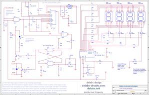
A single Voltmeter or Digital Panel Meter DPM can monitor 8 Analog inputs from sensors or potentiometers using a Mux chip and creating simple digital controls for that. Four pushbuttons on the front panel control the scanner. One 4051 is used to multiplex 8 trimpots that hold the Analog Alarm Settings. The channel number in BCD is translated to a LED channel Display with a 4511 chip.
on: 6/26/2019
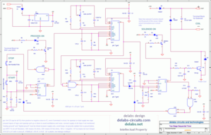
A digital counter monitors the number of times a process goes beyond a certain temperature limit over a long cycle of time. This circuit has a Analog Timer and Digital Counter. The Analog timer turns on an Alarm if the Temperature Limit transition is very long. U1 CD4541 is a Timer with Long Duration Ability. This timer is started by a low pulse from earlier circuit, when the temperature goes above setpoint, a low state is at U2A inputs, this starts the timer.
on: 6/25/2019