Battery Level Indicator
Drag Drop Image anywhere on Screen with Left Button - Zoom in or Zoom out with Scroll Wheel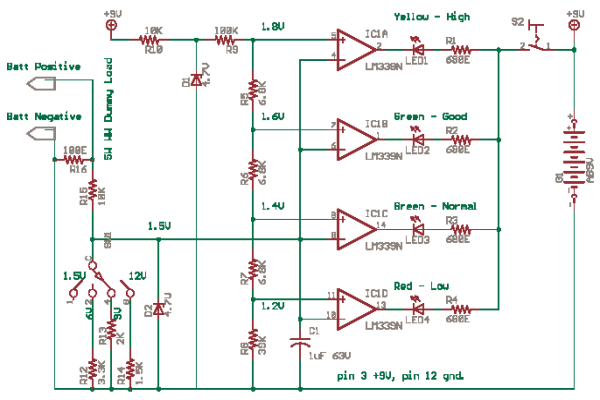
Battery level voltage measurement is best done with a dummy load. This circuit has four LEDs to show the charge left. It is important to avoid overcharge or deep discharge of rechargeable batteries. Never try recharging normal batteries. Using rechargeable batteries are good for the environment.
You can also create an electronic load using a “NPN transistor and Electrolytic cap” with bleeding or discharge resistor. A 555 Timer can turn on NPN for a sec and measure battery voltage as soon as NPN is on. The duty cycle of 555 can be 10% on time. During off-time cap will discharge.
Description - This circuit uses a LM339, a quad comparator. LM339 can work on single or dual supplies, it has a open collector output that can drive 15mA, low power consumption. The circuit is an untested design but it should work.
When you measure the open circuit voltage of a battery with a high impedance DMM (10M), the value may be a bit misleading. Apply a dummy load to bleed the battery a bit so that proper readings can be taken on Load. The load below is a 100 ohms wire-wound fusible ceramic resistor which will heat a bit when you test 12V batteries.
R16 a 5W ceramic wire wound bleeder or dummy load. R15 is a part of an attenuator for obtaining ranges. D2 is a protection clamp diode. R10-D1 forms the 5V reference for comparators. Then an attenuator obtains 1.2, 1.4, 1.6, 1.8 V steps for each comparator. This circuit is similar to Audio Level meter or VU meter circuit.
Battery Charger and Rechargeable Batteries
The comparator compares the battery sample voltage to the fixed reference step. If ‘+’ pin is more positive than ‘-’, or is ‘+’ is more dominant, then output goes floating ‘open collector’, so No LED light . But if ‘-’ is more dominant the output transistor of comparator goes low impedance or saturates or turns ‘ON’. But only spec current can be switched, do not compare with electrical switch ‘ON’. Also on a dual supply 0V is more dominant or positive compared with -12V, even though it appears -12V is a big number. The direction of current is what decides, all measurements are relative.
on: 7/11/2019
analog-design